The soft locator light becomes illuminated when the dimmer is in the off position.
Lutron diva 0 10v led dimmer wiring diagram.
Lutron s new facility management tool empowers you to manage your building from anywhere.
Lutron v compatible diva series led dimmer switch.
Download instructions and wiring diagram here.
The lutron ecosystem dimming wiring diagram.
The diva paddle switch automatically returns to your favorite pre selected light level.
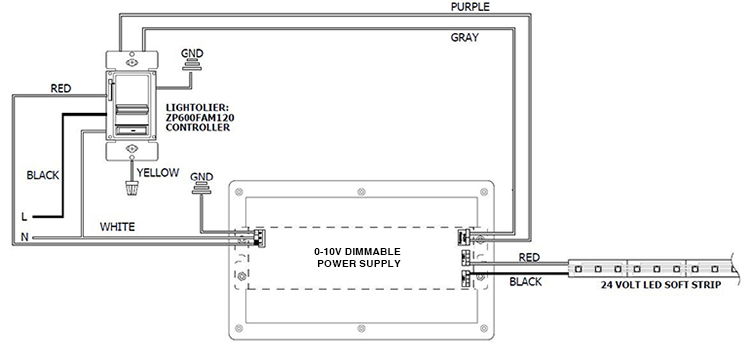
Diva 010 ols w ols dimming with on off control wiring diagram using a power pack 0 10 v ballast driver neutral red red red white red white ground blue black black neutral line hot pp dv pp 347h class 2 only switched hot dimming with on off control for drivers which support dim to off capability power wiring not shown see lighting.
The eco dim model guarantees at least 15 energy savings compared to a standard switch.
1 component 3 components budget friendly costly 20 minutes 5 10 15 20 25 30 35 40 45 50 55 0 50 minutes vs.
Use a wire connector to join one 14 to 18 awg 1 5 to 0 75 mm2 supply wire with one or two 20 awg 0 50 mm2 control wire s.
The diva 0 10v preset dimmer provides dimming control of 0 10v led drivers fl uorescent ballasts and.
Provides 0 10v sinking control for 0 10v fl uorescent ballasts and led drivers.
Carefully push wires into wallbox allowing room for the control back cover.
Lutron 0 10v dimmer wiring diagram lutron diva dvstv v dimmer for fluorescent and led the lutron diva dvstv is a v dimmer that easily lutron dvstv v installation instructions.
Typical 0 10 v dimming sensing switch sensor line voltage wiring low voltage wiring installation time lutron 0 10 v dimming sensing line voltage wiring low voltage wiring vs.
0 10 v is quickly becoming one of the more popular dimming technologies with wired occupancy sensors for v.
Line maestro 0 10v dimming wiring diagram nov 29 horbar.
Single pole or 3 way important.
Increase energy savings and aesthetics with v dimming control to 5.
Wire controls according to the appropriate wiring diagram shown in the wiring section of this sheet and on the ballast.
Each feature is designed around what is most important to you how well your building is working.
5 10 15 20 25 30 35 40 45 50 55 0 switch sensor.
Check out our wiring wizard for step by step instructions videos and wiring diagrams including 3 way for installing a dimmer.